
Vintage Stationary Engines Blog
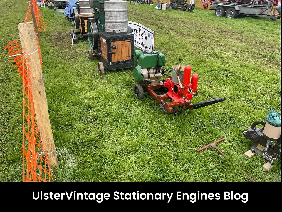
UlsterVintage Stationary Engines Blog
UlsterVintage Stationary Engines
Welcome to UlsterVintage Stationary Engines Videos Playlist.
The Video Playlist below contains 29 Videos of Various Stationary Engines Videos from vintage rallies and Stationary Engines. Just press play and wait till the video finishes then it play 2nd video till all 30 videos are finished our if you just want choose what videos to watch just press 3 lines at top right of video and choose your videos to watch. Feel free share this website our blog with Family and friends.
Welcome to UlsterVintage Stationary Engines Group
The One Stop For all things UlsterVintage Stationary Engines
Please click links below to 👍Like our follow 👉 our view 👀
Our Feel Free to Share this group to your family and friends
Join 👋 https://www.facebook.com/groups/ulstervintagestationary/
view 👀 View Website
Websites
View 👀 http://www.ulstervintagetree.uk
Please Visit our UlsterVintage Stationary Engines Blog at link below where you find videos playlist of Stationary Engines and vintage rallies videos and information about Stationary Engines.
View 👀 https://www.ulstervintage.com/vintage-engines.html
Please Feel Free to tell your family and friends about this group.
Thanks for visiting UlsterVintage Stationary Engines.
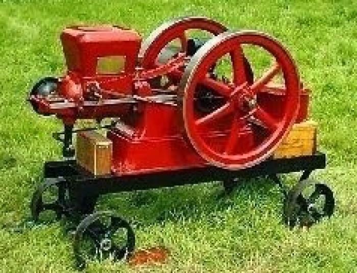
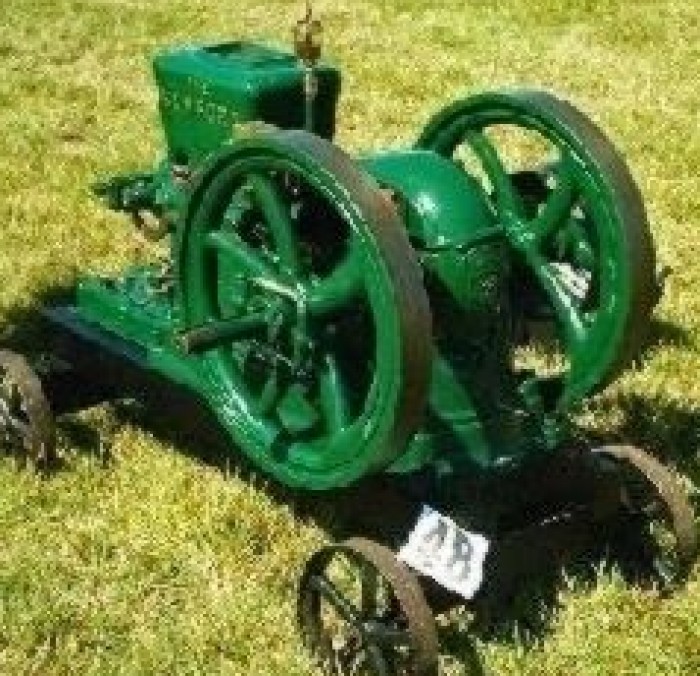
Stationary Engines
Vintage Stationary Engines
Here we provide Stationary Engines articles and videos of the each Stationary Engines on this page just play the video you want in video playlist below you can choose what video by clicking top right corner and choose what video you want.
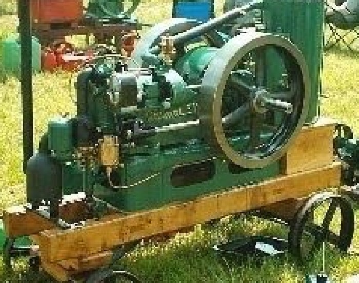
Amanco Engine
Hit-and-miss engines were made by a multitude of engine manufacturers during their peak usage which was from approximately 1910 through the early 1930s when they began to be replaced by more modern designs. Some of the largest engine manufacturers wereStover,Hercules,International Harvester (McCormick Deering), John Deere and Fairbanks Morse.
This is a video montage of the Otto engines running at the Western Minnesota Steam Threshers Reunion (WMSTR), in Rollag, Minnesota. It is a type of hit-and-miss engine.(2min 16sec, 320x240, 340kbit/s video)A hit-and-miss engine is a type of flywheel engine.[1]Aflywheelengine is an engine that has a large flywheel or set of flywheels connected to the crankshaft. The flywheels maintain engine speed during engine cycles that do not produce driving mechanical forces. The flywheels store energy on the combustionstrokeandsupply the stored energy to the mechanical load on the other three strokes of the piston. When these engines were designed technology was not nearly as advanced as today and all parts were made very large. A typical 6 horsepower (4.5 kW) engineweighsapproximately1000 pounds (454 kg). The engine material was mainly cast iron and all significant engine parts were cast from it. Small functional pieces were made of steel and machined to perform their function.[1]
The fuel system of a hit-and-miss engine consists of a fuel tank, fuel line, check valve and fuel mixer. The fuel tank most typically held gasoline but many users would start the engines with gasoline and then switch over to a cheaper fuel such as keroseneordiesel.The fuel line connected the fuel tank to the mixer. Inserted into the fuel line was a check valve which kept the fuel from running back to the tank between combustion strokes. The mixer created the correct fuel/air mixture by means of a needlevalveattachedto a weighted or spring-loaded piston usually in conjunction with an oil-damped dashpot.
Mixer operation was simple, it contained only one moving part, that being the needle valve. While there were exceptions, a mixer did not store fuel in a bowl of any kind. Fuel was simply fed to the mixer, where due to the effect of Bernoulli's principle,itwasself-metered in the venturi created below the weighted piston by the action of the attached needle valve, the method used to this day in the SU carburetor.
Sparks to ignite the fuel mixture are created by either a spark plug or a device called an ignitor. When a spark plug was used, the spark was generated by either a magneto or else a trembler (or 'buzz') coil. A buzz coil used battery power to generateacontinuousseries of high voltage pulses which were fed to the spark plug. For ignitor ignition, either a battery and coil was used or a "low tension" magneto was used. With battery and coil ignition, a battery was wired in series with a wire coil andtheignitorcontacts. When the contacts of the ignitor were closed (the contacts reside inside the combustion chamber), electricity flowed through the circuit. When the contacts were opened by the timing mechanism, a spark was generated across the contactswhichignitedthe mixture. When a low tension magneto (really a low-voltage high-current generator) was used, the output of the magneto was fed directly to the ignitor points and the spark was generated as with a battery and coil.
Lubrication on these early engines was almost always manual (except for very large engines). Main crankshaft bearings and the connecting rod bearing on the crankshaft generally had a grease cup which was a small container (cup) filled with grease andacoverwhich screwed down on the cup.
A typical engine oilerThis is one made by LunkenheimerWhen the cover was screwed down tighter grease was forced out of the bottom of the cup and into the bearing. On very early engines there may have been just a hole in the casting of the bearing capwherelubricatingoil would be squirted while the engine was running. The piston was lubricated by a drip oiler that continuously fed drips of oil onto the piston. The excess oil from the piston ran out of the cylinder onto the engine and eventually ontotheground. Thedrip oiler could be adjusted to drip faster or slower depending on the need for lubrication, dictated by how hard the engine was working. The rest of the moving engine components were all lubricated by oil that the engine operator wouldhaveto apply fromtime to time while the engine was running.
Virtually all hit-and-miss engines were of the "open crank" style, that is, there was no enclosed crankcase. The crankshaft, connecting rod, camshaft, gears, governor, etc. were all completely exposed and could be viewed in operation when the engine wasrunning.Thismade for a messy environment as oil and sometimes grease was thrown from the engine as well as oil running onto the ground. Another disadvantage was that dirt and dust could get on all moving engine parts, causing excessive wear and enginemalfunctions.Frequentcleaning of the engine was therefore required to keep it in proper operating condition.
Cooling of the majority of hit-and-miss engines was by water in a reservoir. There were a small portion of small and fractional horsepower engines that were air-cooled with the aid of an incorporated fan. The water-cooled engine had a built in reservoir(largerenginesusually did not have a reservoir and required connection to a large external tank for cooling water via pipe connections on the cylinder). The water reservoir included the area around the cylinder as well as the cylinder head (most cases)and atank mountedor cast above the cylinder. When the engine ran it heated the water. Cooling was accomplished by the water steaming off and removing heat from the engine. When an engine ran under load for a period of time is was common for the waterin thereservoir toboil. Replacement of lost water was needed from time to time. A danger of the water-cooled design was freezing in cold weather. Many engines were ruined by the forgetful operator neglecting to drain the water when the engine was notin useand the waterfreezing and breaking the cast iron engine pieces. However, New Holland patented a v-shaped reservoir, so that expanding ice pushed itself up and into a larger space, so that the ice wouldn't break the reservoir. Water jacket repairsarecommon on manyof the engines that exist today.
Design
These were simple engines compared to modern engine design. However, they incorporated some very clever designs in several areas, many times because the designer was attempting to circumvent infringing a patent for a particular part of the engine. Thisisparticularlytrue in the area of the governor. Governors were centrifugal, swinging arm, pivot arm, and many others. The actuator mechanism to govern speed was also varied depending on patents existing and the governor used. See, for example, U.S.Patents543,157[2]from 1895 or 980,658[3] from 1911. However accomplished, the governor had one job - to control the speed of the engine. In modern engines, power output is controlled by throttling the flow of the air through the intake by means of abutterflyvalve; theonly exception to this being in diesels and Valvetronic petrol engines. On hit-and-miss engines, the governor holds the exhaust valve open whenever the engine is operating above its set speed, thus interrupting the Otto cycle firingmechanism.
The intake valve on hit-and-miss engines has no actuator. It has a light spring that holds it closed until it can be drawn open when a vacuum occurs in the cylinder. Such a vacuum can only occur when the piston is in a down-stroke and when the exhaustvalveisclosed. (Therefore, when the governor holds the exhaust valve open, the intake valve will not open.) This vacuum causes the intake valve to open, which allows the fuel-air mixture to enter.
Usage
Hit-and-miss engines were made to produce power outputs from 1 through approximately 100 horsepower (.75 - 75 kW). These engines are slow speed and typically ran from 250 revolutions per minute (rpm) for large horsepower engines to 600 rpm for small horsepowerengines.
A Jaeger Trash Pump used for pumping dirty (trashy) water. It has a Hercules 2½ HP (1.9 kW) engine on it. This is an example of an integrated function of hit-and-miss engines (i.e. not belted)They were used to power pumps for cultivation, saws for cuttingwood,generatorsfor electricity in rural areas, running farm equipment and many other stationary applications. Some were mounted on cement mixers. These engines also ran some of the early washing machines. They were used as a labour-saving device onfarms,and allowedthe farmer to accomplish much more than he was previously able to do.
The engine was typically belted to the device being powered by a wide flat belt, typically from 2 - 6 inches (5 - 15 cm) wide. The flat belt was driven by a pulley on the engine that attached either to a flywheel or to the crankshaft. The pulley was speciallymadeinthat its circumference was slightly tapered from the middle to each edge (like an over-inflated car tyre) so that the middle of the pulley was a slightly larger diameter. This design kept the flat belt in the centre of the pulley.
Later history
By the 1930s, more-advanced types of engines were being designed and produced. Flywheel engines were extremely heavy for the power produced, ran at very slow speeds, required a lot of maintenance, and could not easily be incorporated into mobile applications.Inthelate 1920s International Harvester already had the model M engine which was an enclosed version of a flywheel engine. Their next step was the model LA which was a totally enclosed engine (except for the valve system) featuring self-lubrication(oilin thecrankcase), reliable spark plug ignition, faster-speed operation (up to about 750-800 RPM) and most of all, light in weight compared to earlier generations. While the 1½ HP (1.1 kW) model LA still weighed about 150 pounds (68 kg), it was farlighterthanthe model M 1½ HP engine, which is in the 300-350 pound (136 - 159 kg) range. Later a slightly improved LA, the LB was produced. The models M, LA and LB were throttle governed. As time passed, more engine manufacturers moved to the enclosedcrankcaseengine.Companies like Briggs and Stratton were also producing lightweight air-cooled engines in the 1/2 to 2 HP (.37 - 1.5 kW) range and used much lighter-weight materials. These engines also ran at much higher speeds (up to approximately 2000–2500RPM)and thereforeproduced far more power per pound than the slow flywheel engines.
With the exception of oil field applications, flywheel engine production ceased in the 1940s.
Preservation
Although thousands of out-of-use flywheel engines were scrapped in the iron and steel drives of World War II, many survived to be restored to working order by enthusiasts. However in recent years engines with original paint have become more desireabletomanycollectors than repainted engines. Numerous preserved hit-and-miss engines may be seen in action at shows dedicated to antique engines (many have antique tractors too) as well as in the stationary engine section of steam fairs and vintage vehicle rallies.
Bamford Engine
JCB (formally J C Bamford Excavators Limited)[3] is a British Multinational corporation, with headquarters in Rocester, Staffordshire, engaged in the manufacture of equipment for construction, demolition and agriculture. It is the world's third-largest
construction equipment manufacturer.[4] It produces over 300 types of machines, including diggers (Backhoes), excavators, tractors and diesel engines. It has 18 factories across Asia, Europe, North America, and South America; its products are sold in
over 150 countries.[2][5]
The firm was founded in 1945 by Joseph Cyril Bamford, after whom it is named, and continues to be owned by the Bamford family. In the UK 'JCB' is often used colloquially as a generic description for mechanical diggers and excavators and now appears in
the Oxford English Dictionary, although it is still held as a trademark.[6]
History
20th century
The firm was founded by Joseph Cyril Bamford in October 1945 in Uttoxeter, Staffordshire, England. He rented a lock-up garage 12 feet by 15 feet. In it, using a welding set which he bought second-hand for £1 from English Electric, he made his first vehicle,
a tipping trailer from war-surplus materials. The trailer's sides and floor were made from steel sheet that had been part of air-raid shelters. On the same day as his son Anthony was born, he sold the trailer at a nearby market for £45 (plus a part-exchanged
farm cart) and at once made another trailer. At one time he made vehicles in Eckersley's coal yard in Uttoxeter. The first trailer and the welding set have been preserved:
JCB's first welding set
The first vehicle JCB made (a farm trailer)
In 1948, six people were working for the company, and it made the first hydraulic tipping trailer in Europe. In 1950, it moved to an old cheese factory in Rocester, still employing six. A year later, he began painting his products yellow. In 1953, his
first backhoe loader was launched, and the JCB logo appeared for the first time. It was designed by Derby Media and advertising designer Leslie Smith. In 1957, the firm launched the "hydra-digga", incorporating the excavator and the major loader as a
single all-purpose tool useful for the agricultural and construction industries.[7]
In 1960, JCB's hydraulic tractors entered the North American market, proving a long-lasting success. JCB became, and still is, the brand leader in the world. By 1964, JCB had sold over 3,000 3C backhoe loaders. The next year, the first 360-degree excavator
was introduced, the JCB 7.[8]
In 1978, the Loadall machine was introduced. The next year, JCB started its operation in India. In 1991, the firm entered a joint venture with Sumitomo of Japan to produce excavators, which ended in 1998.[9] Two years later, a JCB factory was completed
in Pooler near Savannah, Georgia in the USA, and the next year a factory was opened in Brazil.
21st century
Production of the first engine designed and manufactured by JCB, the JCB444 diesel engine, started in 2004.[10] In 2005, for the first time in nearly forty years, JCB bought a company, purchasing the German equipment firm Vibromax. In the same year, the
firm opened a new factory in Pudong China . By 2006, the firm had 4000 employees, twice what it had in 1975.
Planning of a new £40 million pound JCB Heavy Products site began in 2007,[11] and by the next year, the firm began to move from its old site in Pinfold Street in Uttoxeter to the new site beside the A50; the Pinfold Street site was demolished in 2009.
During that year, JCB announced plans to make India its largest manufacturing hub. Its factory at Ballabgarh in Haryana, was to become the world’s largest backhoe loader manufacturing facility.[12]
The firm shed 2,000 jobs during the recession, but in 2010 it announced it was recruiting up to 200 new workers.[13]
Operations
JCB factory and park at Rocester
The Fossor, at the JCB headquarters in RocesterJCB has 18 factories in the UK, Germany, North and South America, India, and China.[5] The company employs some 7,000 people on four continents and sells its products in 150 countries through 1500 dealer
depot locations. The company has a range of more than 300 products.[14]
The firm is headquartered in Rocester, United Kingdom, which is also the production site for backhoe loaders and telescopic 'Loadall' handlers. It has a further three factories in nearby Cheadle, Staffordshire (JCB Earthmovers, JCB Landpower and JCB Compact
Products), one in Rugeley (JCB Cab Systems), three in Uttoxeter (JCB Attachments, JCB Heavy Products and JCB World Parts Centre), one in Foston in Derbyshire (JCB Power Systems) and one in Wrexham in North Wales (JCB Drivetrain Systems).
Its Indian factories are based in Ballabgarh (Haryana) and Pune, its US factory is in Pooler, Georgia, its Brazilian factory in Sorocaba, and its Chinese factory was completed in 2005 in Pudong near Shanghai. JCB also owns Vibromax, a German compaction
equipment company based in Gatersleben.
The company has also licensed its name and image to a line of consumer power tools, manufactured by Alba PLC.
The products are sold through franchised dealerships, many of which are often exclusive and cover whole countries.[15]
Products
Many of the vehicles produced by JCB are variants of the backhoe loader, including tracked or wheeled variants, mini and large versions and other variations for carrying and moving items, for example fork lift vehicles and telescopic handlers for moving
materials to the upper floors of a building site. Wheeled loading shovels and articulated dump trucks are also produced.
Excavators
Tracked 360° excavators ranging from the JZ70 (7 tonne zero tail swing excavator) to the JS460 (46 tonne tracked excavator). In 2008 at Con expo JCB revealed a new top range JS520 which included the new style paintjob with rams painted black (nadimwilson
c). Wheeled 360° excavators ranging from the JS130W to the JS200W. Machines can be produced with either monoboom or a triple articulated boom.
Wheeled loaders
Industrial and agricultural wheeled loaders from compact 6 tonne hydrostatic machines to larger 25 tonne quarrying machines using a mix of 4 and 6 cylinder diesel engines.
Tractors
JCB Fastrac 8250 tractorJCB has also made its name in the tractor world by producing one of the first such machines that features proper suspension and is capable of travelling at speed on roads. The JCB Fastrac entered production in 1990. Prior to this
design, the suspension was difficult because of the fixed-height connections required to farm machinery, and tractors were notoriously slow on the roads. Dependent on the model, the Fastrac can travel at 50 km/h, 65 km/h or 75 km/h (40 mph). The machine
was featured on the BBC television programme Tomorrow's World. From 2006 the company also produces a range of compact tractors designed for grounds-care, horticultural, and light agricultural duties.
Military vehicles
JCB also makes a range of military vehicles, which also concentrate on load-handling and excavation.[16] These include the JCB HMEE.
JCB Dieselmax
JCB Dieselmax on display at the Heritage Motor CentreMain article: JCB Dieselmax
In April 2006, JCB announced that they were developing a Diesel-powered Land Speed Record vehicle known as the 'JCB Dieselmax'. The car is powered by two modified JCB 444 diesel powerplants using a two-stage turbocharger to generate 750 bhp, one engine
driving the front wheels and the other the rear wheels.
On August 22, 2006 the Dieselmax, driven by Andy Green broke the diesel engine land speed record, attaining a speed of 328.767 mph (529 km/h). The following day, the record was again broken, this time with a speed of 350.092 mph (563.418 km/h).
JCB Vibromax
JCB acquired the German company Vibromax, which manufactures compaction equipment.
JCB Phones
JCB licenses its brand for a series of rugged feature phones and smartphones targeted at construction personnel. The design and marketing contract was awarded to Data Select in 2010.[17]
Marketing
Logo
The JCB logo dates from 1953; from 1960 the company typewriters were given an extra key to render it accurately. The company has mainly advertised in the trade publications and their advertisements have won many awards, particularly for photography. The
logo was designed by Leslie Smith, and is off-set at 18 degrees from the horizontal and 22 degrees from the vertical - the angles Joe Bamford liked.
Display team
To demonstrate his faith in the hydraulic failsafes on JCB machines (which lock the arms in the event of a loss of hydraulic pressure, preventing them from crashing to the ground), Joe Cyril Bamford arranged to have several backhoes raise themselves up
on their arms, and drove his car beneath them.[citation needed]
This has since developed into a world famous demonstration of the versatility of the backhoe configuration. The JCB display team (JCB Dancing Diggers) tour agricultural shows and produce videos, showing some of the unusual ways in which such vehicles
can support themselves or manoeuvre. For example, it is quite common for drivers to support the vehicle on both buckets, either for turning on the spot without damaging ground, or for spinning the tracks in a puddle to clean them. The display team expanded
this concept into a sort of vehicle gymnastics. The drivers are members of JCB's demonstration team, who visit prospective customers and demonstrate machines on the customer's property in order to prove the machine's suitability for the task at hand.[citation
needed]
JCB Insurance Services Ltd
JCB Insurance Services was founded in 1984 by JCB Chairman Sir Anthony Bamford as a fully owned subsidiary of to provide for the insurance needs of the customers purchasing the firm's equipment, with the funding they obtained from another fully owned
subsidiary, JCB Finance. The insurance subsidiary provides all-risks policies, with optional additions for road risks coverage, and for Public liability and employers liability.[18] [19]
JCB Academy
Main article: JCB Academy
JCB is the sponsor of JCB Academy, a new secondary school in Rocester which had its first intake of pupils in September 2010.[20]
In popular cultureIn 1958 the singer Lenny Green had a song called JCB and Me.In UK version of the Teletubbies one of the live-action visual 5-minute segments (seen from a Teletubby belly) featured number counting involving vehicles in lines. A row of
JCBs are seen in line, their hydraulics operated as if they are 'dancing'.JCB is prominently featured in the song entitled "JCB" by the music group Nizlopi, which has achieved UK Number One status. The song is about a boy who goes to work with his father
for the day.A JCB (not talking) named Jekub appears in volume 2 (Diggers) of The Bromeliad (alias Nomes) series by Terry Pratchett.The Lego Technic range featured a scale-model of the JCB backhoe (Set 8862), complete with working hydraulics systems (simulated
using pneumatics) and many other features of the original.In series 9 of Top Gear, Jeremy Clarkson bought a JCB Fastrac 8250 for a challenge involving "growing your own petrol". Jeremy Clarkson, James May, and Richard Hammond all had to reverse their
vehicles around the Top Gear car park.The song "McCavity" [21] by the UK group The Macc Lads contains the line "He's filled more holes than a JCB" to (rather crudely) demonstrate the sexual prowess of the band-member being sung about.One digger stars
in the music video Sunday Morning - 1985 hit song by The Bolshoi. Three band members are standing on this 360-degree excavator while Trevor Tanner (the singer) is lying on the sofa.
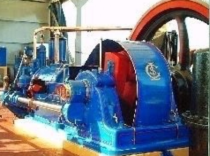
Crossley Engine
Crossley, based in Manchester, United Kingdom, was a pioneering company in the production of internal combustion engines. Since 1988 it has been part of the Rolls-Royce Power Engineering group.
More than 100,000 Crossley oil and gas engines have been built.
History
Crossley Brothers
A Crossley 1/2hp engine from 1884
Crossley Brothers was set up in 1867 by brothers Francis (1839-97) and William J.(1844-1911). Francis, with help from his uncle, bought the engineering business of John M Dunlop at Great Marlborough Street in Manchester city centre, including manufacturing pumps, presses, and small steam engines. William (Sir William from 1910 - Baronet) joined his brother shortly after the purchase. The company name was initially changed to Crossley Brothers and Dunlop. Each of the brothers had served engineering apprenticeships: Francis, known as Frank, at Robert Stephenson and Company; and William at W.G. Armstrong, both in Newcastle upon Tyne. William concentrated on the business side, Frank provided the engineering expertise.
The brothers were committed Christians and strictly teetotal, refusing to supply their products to companies such as breweries, whom they did not approve of. They adopted the early Christian symbol of the Coptic Cross (Coptic Christianity) as the emblem to use on their road vehicles.
In 1869 they had the foresight to acquire the UK and world (except German) rights to the patents of Otto and Langden of Cologne for the new gas fueled atmospheric internal combustion engine and in 1876 these rights were extended to the famous Otto four-stroke cycle engine. The changeover to four stroke engines was remarkably rapid with the last atmospheric engines being made in 1877.
The business flourished. In 1881, Crossley Brothers became a private limited company (i.e. Crossley Brothers Ltd.), and then in 1882 it moved to larger premises in Pottery Lane, Openshaw, in eastern Manchester.
Further technical improvements also followed, including the introduction of poppet valves and the hot-tube ignitor in 1888 and the introduction of the carburettor, allowing volatile liquid fuels to be used.
By adopting the heavier fuelled "oil" engine, the first one being demonstrated in 1891, the company's future was assured. Among other applications, these "oil" engines were used with Gwynnes Centrifugal Pumps for irrigation.[1] Then in 1896, they obtained rights to the diesel system, which used the heat of compression alone to ignite the fuel. Their first diesel was built in 1898.
By the turn of the century, there was also some production of petrol engines, and from 1901 these engines were finding their way into road vehicles, including, in 1905, Leyland buses.
A major contribution to manufacturing was the introduction of the assembly line. The Crossley system even influenced Henry Ford, who visited Pottery Lane at the turn of the century.
Crossley 9T 25/30 HP Phaeton 1920
An AEC Regent V badge-engineered into a Crossley Regent bus after AEC absorbed Crossley Motors
Crossley Motors
Main article: Crossley Motors
In 1904 the company started production of motor cars and a separate company, Crossley Motors Ltd. was registered on the 11th April 1906.
This company was sold to Associated Equipment Company (AEC) in 1948, and vehicle production continued until 1958.
Crossley Premier
In 1919 Crossley Brothers bought Premier Gas Engines of Sandiacre, Nottingham, who built very large engines, and in 1935 changed their name to Crossley Premier Engines Ltd. The Nottingham factory was expanded, and production continued there until 1966.
The engines were large horizontal heavy oil engines, typically used as generating plants or to power industrial plant such as air compressors, water pumps or mills. They were produced in a range of sizes, based on a standard cylinder unit, as either in-line or horizontally-opposed cylinder engines.[2] They had clerestory combustion chambers with single inlet and exhaust valves above and below the chamber. Other manufacturers at the time, notably Brush, produced very similar engines as modular, opposed cylinder units. Crossley's were distinctive for using a monobloc head on each cylinder, although this was in the form of a self-supporting wet liner and the water jacket around the whole cylinder bank was a separate casting. The engines were also unusual for being one of the few practical applications of an electrically-driven supercharger.[2] This gave a relatively low boost pressure and was more of a scavenge blower, but it could increase output power by up to 50%.[2]
A pair of 16 cylinder opposed engines of 3,500 bhp, built for electrical generation in Jerusalem in the 1930s, were at the time the largest oil engines in the world.[2] Like the earlier Ferranti steam generating plants, these placed half of the engine each side of a centrally-mounted alternator, thus reducing the maximum load on the crankshaft. A similar engine in a bombproof underground shelter was used to power the wartime Aspidistra transmitter.[3]
By the 1960s, although sales remained reasonable, the company had become unprofitable. The design of the engines then being made was essentially 40 years old, so in 1962 agreement was reached to use the French Pielstick design. Production of these engines, intended for ships, railway locomotives and electricity generation, was initially carried out at Nottingham. But, before the engines could become established, the money ran out and the company had to call in the receivers. A purchaser was found in Belliss and Morcom Ltd. but the name Crossley-Premier was kept.
The market for engines was continuing to shrink, and in 1968 the new company joined the Amalgamated Power Engineering (APE) group and the name became APE-Crossley Ltd. For the first time the new company used the Coptic Cross logo on the engines. Previously, this had only appeared on Crossley Motors products — the rights to use it had to be bought from British Leyland. APE, in its turn, became part of Northern Engineering Industries (NEI) in 1981, and the company name became the unwieldy NEI-Allen Limited – Crossley Engines.
Rolls-Royce Power Engineering[edit]
NEI themselves, in 1988, were taken over by Rolls Royce plc, and the company became part of the Allen Power Engineering - Crossley Engines division of the Rolls-Royce Industrial Power Group. This, in turn, became Crossley Engines division of Rolls-Royce Power Engineering, continuing to produce the Crossley-Pielstick range until 1995.
The Crossley Works on Pottery Lane was closed on 27 February 2009, with what remains of the business being relocated to a Rolls-Royce factory in Dunfermline. Demolition of the works began in December 2009.[4]
Diesel engines
Crossley Brothers built diesel engines for stationary, marine and locomotive use. There was a wide range of engines from six to 3200 horsepower (Crossley) and up to 9000 horsepower (Crossley-Pielstick}.[5]
Their marine engines had a reputation for durability and reliability. However, their rush to be a part of the emerging railway traction market was an umitigated disaster.
Crossley apparently took one of its successful World War II Patrol Boat motors and re-engineered it for railway service. This resulted in the construction of;
the HSTVee-8, used in the British Rail Class 28, the CIE 001 Class and the WAGR X class
the ESTVee-8 used in the CIE 201 Class
the ESNT6 used in British Rail Class D3/3 shunting locomotives
All three were two stroke engines equipped with Crossley's system of exhaust pulse pressure charging whereby surplus air in the exhaust manifold was forced back into the cylinder by the exhaust pulse from a neighbouring cylinder.
Crossley's foray into traction motor construction was less than successful, with all but those installed in the WAGR X class having a very short working life. Motor failures occurred within months of the various classes being introduced. The WAGR Crossleys underwent over 600 modifications in their service life. The CIE 001 Class were re-motored with EMD engines between 1968 and 1971 and the CIE 201 Class between 1969 and 1972
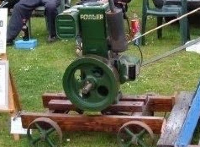
Fowler Engine
John Fowler & Co Engineers of Leathley Road, Hunslet, Leeds, West Yorkshire, England produced traction engines and ploughing implements and equipment, as well as railway equipment. Fowler also produced the Track Marshall tractor which was a tracked
version of the Field Marshall. British Railways Engineering Department locomotives ED1 to ED7 were built by Fowler.
History
Main article: John Fowler (agricultural engineer)
John Fowler was an agricultural engineer and inventor who was born in Wiltshire in 1826. He worked on the mechanisation of agriculture and was based in Leeds. He is credited with the invention of steam-driven ploughing engines. He died 4 December 1864, following a hunting accident. After his death, John Fowler & Co., was then continued by Robert Fowler and Robert Eddison. In 1886 the limited company of John Fowler & Co., (Leeds) Ltd., was formed. It merged with Marshall, Sons & Co., Ltd., of Gainsborough in 1947 to form Marshall-Fowler Ltd.
Although not well-known for them, Fowler also built a small number (117 has been claimed) of steam wagons. These were vertical-boilered, with an unusual single-crank cross-compound vee-twin engine. At least one was preserved, as part of the Tom Varley collection.
During the Second World War, the Hunslet factory also produced Matilda tanks for the Army. Production finally ceased in early 1974.[1]
Preservation
Railway locomotives
Some locations of preserved Fowler railway locomotives include:
AustraliaBennett Brook Railway, a tourist railway in Perth, Western Australia
Leeds Fowler 11277: restored in Bundaberg, Australia
Leeds Fowler, 0-6-0T, "Faugh-a Ballagh", preserved at Port Douglas, Australia.[2]
BrazilRailway Museum in Jundiaí, SP (Brazil). Builder plates #1531 from 1870, she's a 4-4-0 for 5 ft 3 in (1,600 mm) gauge. Built for Companhia Paulista de Estradas de Ferro where she spent all of her active life and as CP's first locomotive she was numbered #1.
GermanyOpen Air Museum "Freilichtmuseum am Kiekeberg", near Hamburg, Germany
New ZealandTokomaru Steam Museum, Tokomaru, New Zealand
Silver Stream Railway, Wellington, New Zealand
PakistanChanga Manga Forest Railway, Pakistan [3]
United KingdomAmberley Museum Railway
Bredgar & Wormshill Light Railway
East Kent Railway (heritage)
Middleton Railway – two Fowler locomotives
Phyllis Rampton Trust
Pontypool and Blaenavon Railway
One of two 18-gauge steam locomotives used to transport concentrates at the De Beer mine, KimberelySouth AfricaMine Museum Kimberely – two 0-4-2WT Fowler locomotives
Traction engines
The Iron Maiden - a Fowler & Co. -built Showman's engine which was featured in the film The Iron Maiden is exhibited as part of the Scarborough Fair Collection of Fairground organs and machinery at events such as the Great Dorset Steam Fair.
The Melbourne Steam Traction Engine Club of Melbourne, Victoria, Australia, a volunteer organisation dealing with the preservation of Australia's mechanical heritage, has a number of Fowler Traction Engines and Steam Rollers in preservation, some privately owned by members, and some owned by the club. Most are in restored, operating condition and are demonstrated to the public regularly. Club engines include one of a pair of Z7 ploughing engines.
Ruston Engine
Ruston, Proctor and Company was established in Lincoln, England in 1857, and were manufacturers of steam tractors and engines. They later became Rustons and then Ruston & Hornsby.
History
A portable engine by Ruston, Proctor & Co.
Ruston, Proctor and Co. engine at Cromford steam fair 2008
The firm started as millwrights and implement manufacturers 'Burton & Proctor' in Lincoln in 1840. Joseph Ruston became a partner in the company in 1857, and the company changed name to Ruston, Proctor & Co. and grew to become a major agricultural engineering firm.
In 1918 the firm merged with the established Richard Hornsby & Sons company, from Grantham, Lincolnshire.
Rustons were primarily steam engineers, manufacturing portable, stationary and traction engines, boilers, and associated engineering products such as winding gear, shafts and pulleys. Threshing machines, clover hullers, corn mills, maize shellers and pumps for steam power were also made. As well as engines for agriculture machines Rustons made railway locomotives, industrial equipment and mining machinery. The company also expanded into electrical and diesel engineering.
The firm were one of the first to manufacture steam-powered excavating machinery – in the 1880s producing the "Dunbar & Ruston's" steam navvy (excavator).[1] These 2 cu yd machines were used in the construction of the Manchester Ship Canal. In 1906 they built the "Ruston Light Steam Shovel", and exhibited it at the Royal Agricultural Show of 1907 held in Lincoln, the machine being of 3/4 cu yd capacity.
The firm later became Ruston-Bucyrus.
Preserved machines
Ruston Proctor reg. no. CT3949 traction engine no. 33189.
Ruston Proctor works no. 51168 (1916) petrol locomotive with Phyllis Rampton Trust.
Ruston Proctor flywheel drive to overhead belts: Sapucai Steam Train Maintenance Depot, Paraguay.
See also
Ruston & Hornsby
Ruston (engine builder)
Gardner engine
L. Gardner and Sons Ltd was a well-known British builder of diesel engines for stationary, marine, road and rail applications. The company was founded in Hulme Manchester England in 1868. They started building engines around 1895. The firm of L. Gardner
& Sons ceased engine production in the mid-1990s.
Origin
The Gardner engine of X24
About 1868 Lawrence Gardner set up as a sewing machine maker in Upper Duke Street, Stretford Road, Hulme, Manchester. He died in 1890, but the business was continued by his sons under the name L. Gardner & Sons Ltd.
Gas and diesel engines
From about 1895 the company was building gas engines and, in 1899 it moved into Barton Hall Engine Works, Patricroft, Manchester.
In 1903 it became a limited company, L Gardner and Sons Ltd. Norris and Henty Ltd, of London, were appointed as sales agents.
Diesel engine production began in around 1903. In 1912 a new sales subsidiary, Norris, Henty and Gardners Ltd, was formed.
During World War I (1914–1918) the company made munitions and parts for heavy guns and engines for tanks.
Automotive engines
During the 1920s there was rapid development in the design of diesel engines. In 1929 a Gardner "4L2" marine engine was fitted into a Lancia bus. This conversion was successful and prompted Gardner to introduce the "LW" series of diesel engines, designed especially for road vehicles but later modified and supplied as a marine engines with factory-fitted bilge pumps.
During World War II (1939–1945) Gardner's war work consisted mainly of building diesel engines of their own design. Their bus engines were also used as the main powerplant in the Royal Navy's X class and XE class midget submarines.
Post-war diesels
A Sectioned 6LW of 1961 at the Anson Engine Museum from a Bristol Commercial Vehicles bus.
After the war the 'LW' diesel engine continued to be built in large numbers for lorries and buses and was later supplemented by the more modern 'LX'. The larger '6L3' and '8L3' engines were used in railway locomotives, such as British Rail Class 01 and British Rail Class 04 and also in vessels of up to 120 feet such as MV Havengore, and the famous maxi yachts Condor and Condor of Bermuda, S.Y. Crescent and others.
The supply of remanufactured Gardner engines and Gardner parts[edit]
L. Gardner and Sons ceased production of new engines in the early 1990s. The introduction of emissions regulations for road-going Gardner diesels would have required the development of significantly modified or totally new engine designs, and in the marine market there was a shift away from big, low-speed, high-torque engines such as Gardners towards adapted high-speed automotive turbodiesels. Two spin-off firms from the original company are still in existence. Gardner Marine Diesels [1] overhauls, re-manufactures and installs a wide range of marine-spec Gardners and both they and Walsh Engineering [2] supply genuine Gardner engine parts for all types of Gardner engines worldwide. Another firm, Marine Power Services.[3] specialise in the restoration and marinisation of Gardners for the inland waterways and the manufacture of component castings incl LW range exhaust, intake and water manifolds. Another firm, Gardner Enthusiast Ltd, manufactures piston rings, engine valves and major engine castings, including marine manifolds for the 8LXB. Gardner Enthusiast Ltd also supply engine castings to Gardner Parts Ltd.[4]
gardner Engines
Gardner 6LXB, 180 hp @ 1850 RPM, Natural 6-cylinder diesel, Cylinder Capacity: 10,450cc
Engines used in Buses[edit]
Gardner 6LXB, Leyland Gearbox, Leyland Titan TNLXB2RRSP,Park Royal. London Regional Transport T1-T250
Gardner 6LXB, Leyland Gearbox, Leyland Titan TNLXB2RR,Leyland. London Regional Transport T251-1125
Gardner 6LXB, Voith DIWA851, Dennis Dominator 9.4m, Duple Metsec W29, Kowloon Motor Bus DM1-DM40
Gardner 6LXB, Voith DIWA851, Dennis Jubilant, Walter Aexander, Duple Metsec, Kowloon Motor Bus N5-N364
Gardner 6LXB, Voith DIWA851, Leyland Victory-2, Walter Alexander CB, China Motor Bus LV1-LV167
Gardner 6LX, Leyland Gearbox, Guy Victory-2, BUSAF, Kowloon Motor Bus G1-G4
Gardner 6LXB, Voith DIWA851, Leyland Victory-2, Walter Alexander KB, Kowloon Motor Bus G5-G544
Gardner 6LXB, Voith DIWA851, MCW Metrobus DR102, MCW Apollo MkII, Kowloon Motor Bus M1-M20,M22,M23,M25-M29,M31-M44,M47-M57,M59,M60,M62,M65-M70,M73,M78-M88
Preservation
The Anson Engine Museum has an extensive collection of historic Gardner engines.
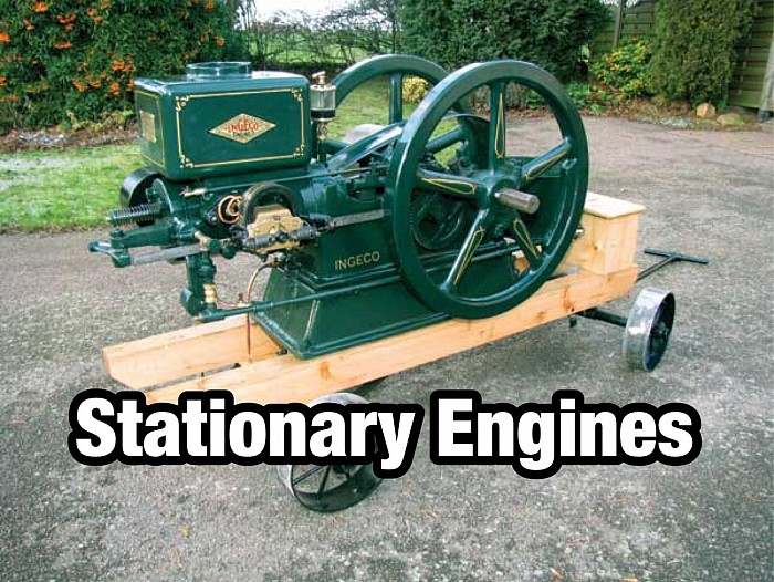
Ingeco Engine
To start, we need a brief introduction into the International Steam Pump Co. since the International Gas Engine Co. (Ingeco) was one of their subsidiary branches.
In 1899 the International Steam Pump Co. was formed. It was made up of a number of other smaller steam pump companies including Blake & Knowles Steam Pump Works of Cambridge, Mass.; Deane Steam Pump Works of Holyoke, Mass.; Henry R. Worthington Co. of Harrison, N.J.; Laidlaw-Dunn-Gordon Co. of Cincinnati, Ohio; Snow Steam Pump Works of Buffalo, N.Y.; Holly Manufacturing Co. of Buffalo, N.Y.; Clayton Air Compressor Works of Brooklyn, N.Y.; as well as the Power and Mining Machinery Co. of Cudahy, Wis.
At the time, this accounted for 90 percent of the steam pump industry in the United States. The reports for the fiscal year ending on March 31, 1906 showed profits for the company at $2,255,312 compared with $1,617,435 in 1905, showing that the company was on the right track. As with many big companies that try to expand faster than they should, they got themselves into trouble. In 1909, the International Steam Pump Co. issued $8,500,000 in bonds to refund their debt of $4,500,000 and retire a floating indebtedness of $1,498,000 in notes. They also provided cash for the payment on a new factory, as well as improvements.
In 1910, the company’s capital stock was $39,000,000 and Mr. John Wesley Dunn was president; the company seemed to have recovered.
Ingeco engines
The International Gas Engine Co. (Ingeco), of Cudahy Wis., appeared in the gas engine community in early 1912 with a vast line of stationary engines, including pushrod style farm engines, sideshaft engines and vertical engines. The vertical and horizontal engines were available as hopper-cooled as well as tank cooled. Ingeco built a horizontal air-cooled engine as well. The diversity of fuel usage in this line of engines included gas, gasoline, oil and producer gas. The company featured horsepower ratings to fit the needs of almost anyone, including sizes from 1-1/2 to 350 horsepower.
By mid-1913 the Ingeco line included the following: a horizontal, hopper-cooled farm engine that was built in sizes 1-1/2, 2-1/2, 4, and 6 HP, and available in either hit-and-miss or throttle governing; a horizontal hopper-cooled sideshaft engine built in the sizes 6, 8, 10, 12 and 15 HP; a tank-cooled sideshaft engine built in 12 sizes ranging from 6 to 60 HP; hopper-cooled and tank-cooled vertical engines built in the 2, 4 and 6 HP sizes; and much larger tank-cooled multi-cylinder vertical engines up to 350 HP. The horizontal air-cooled engine was built only in the 1-1/2 HP size.
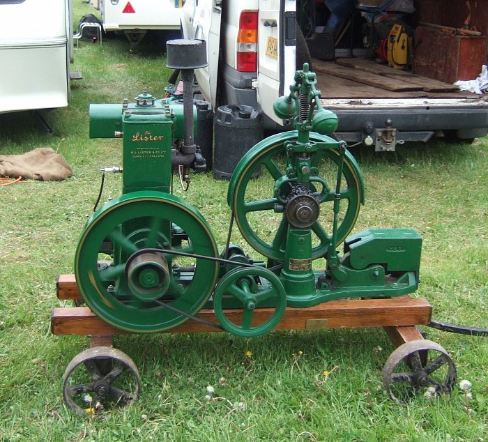
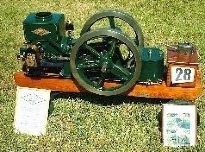
Lister Engine
Lister Engine
Perhaps the most-well known stationary engine brand, the firm of R.A. Lister was originally founded by Ashton Lister in 1867, and basically made anything required, but by 1900, the manufacture of cream separators, dairy & general agricultural equipment
had established the firm.
As regards engines, Listers initially held an agency for the Yeovil firm of Petters, selling the horizontal Handyman range, but soon decided to introduce their own range. Listers' first engine was in fact an American designed Stover sold under the Southwell name, a company who Lister took over in 1908, but their own first design was launched in 1909. Lister seemed to concentrate on vertical engines, largely ignoring horizontals designs that were prevalent at the time.
One feature of all Lister designed engines was a robust construction and ease of access to all vital parts. Features such as twin flywheels on the A & B models enabled fitting of pulleys on either or both sides to drive 2 separate machines. The A was introduced in the early 20s and the B followed in 1924, production of the latter finally ceasing in 1962.
Of course the longest running model was the ubiquitous D type which was introduced in 1926 at engine number 80 000 and ran until 1964, which must have been one of the longest and largest production runs of any single type of engine. Available with either hopper, tank or radiator cooling, in petrol, paraffin or TVO forms, and in a variety of horsepower outputs dependent on engine speed, this was the most versatile agricultural engine ever produced in the UK. With its higher-speed industrial brother, the Model F, most applications could be catered for.
1n 1929, the start of what was to become an immensely popular range of small diesel engines was introduced. These had significant cold-starting improvements over other manufacturers engines. These engines came to be known as the CS diesels and were branded in a output/cylinder format e.g. 5/1 for 5bhp/single cylinder.
In the immediate post-war years, as sales of Petters air-cooled A series engines grew, sales of equivalent 11/2-21/2hp Lister engines dropped off, so an agreement was made to import and latterly manufacture under licence, the American Wisconsin range of lightweight air-cooled engines. These resemble Villiers, BSA or Jap engines of the same period and we almost threw one away thinking it was a little Villiers until a friend realised what we had been given. Now it is awaiting restoration.
Listers eventually became part of the Hawker Siddley Group, which included Mirrlees (who took over Blackstones) National, Gardner & Petter. Indeed Lister became known as Lister Petter, still occupying the premises at Dursley in Gloucestershire. In recent years, there have been several imminent collapses and at the time of writing, I'm unable to confirm status of the company.

Petter Engine
Petter Engine
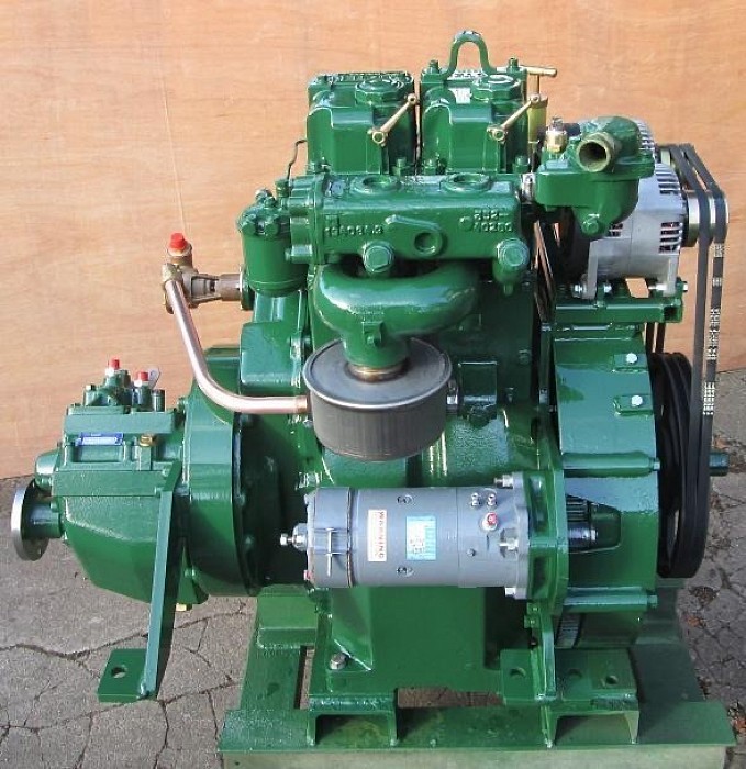
Lister Petter is a British company that manufactures internal combustion engines for industry.
It was formed in 1986 from the merger of Petters Limited and R A Lister and Company. At that time the company was part of the Hawker Siddeley group, but today L-P is independent. Its products are small diesel engine market, ranging from single-cylinder water-cooled engines of 2.7 horsepower (the 'Zeta' series) up to the 64 horsepower (48 kW) 'Delta' engine. One higher-power engine of up to 335 horsepower (250 kW), the 'Omega' is also produced under licence. The engine designs range from more recent design high-speed turbodiesels (such as the 'Gamma' or 'Omega' engines) to traditional single-cylinder medium-speed types such as the 'A-Series' and 'Phi' types.
Applications
Lister Petter engines are generally used in stationary industrial applications such as pumping and electricity generation. The company produces a range of complete generator sets, units equipped for welding and in-house pumping sets, as well as supplying engines to other equipment manufacturers. L-P engines are widely exported[citation needed], especially for use in irrigation projects[citation needed]. The company also maintains a long tradition (of both its founder companies) in supplying engines for marine applications both as prime mover engines for small vessels and as auxiliary power units in larger ones.
Gas-fuelled engines
Lister Petter's main product[citation needed], the 'Alpha' series of sub-2-litre engines, is also available in spark ignition forms for running on natural gas or propane. L-P also manufactures and sells biodiesel plants, allowing customers to produce their own fuel for diesel engines.
History
1867 R A Lister company founded by Robert Ashton Lister.
1893 James B Petter & Sons founded.
1895 First oil engines made by Petters.
1910 Petters Ltd founded.
1929 First diesel engines produced by R A Lister in Dursley.
1986 R A Listers and Petters Ltd merged to form Lister Petter Ltd.
2004/2005 Lister Petter sees unprecedented growth and re-investment in its core products.
Lister & Petter engines were workhorses of the British Commonwealth[citation needed]; many of these engines[citation needed] are still in use today in dump trucks[citation needed], generators[citation needed] and water pumps[citation needed]. They generally, but not exclusively, leave the factory in a Mid Brunswick Green colouring.
Engine ranges
One of the most popular[citation needed] early Petter engines was the AVA series, AVA1 and AVA2 (1- and 2-cylinder engines respectively), and the Lister D. The majority of these engines were hand-crank start and fully mechanical, without any electronics or electrical controls. Engines like this, if not still working, are now considered collectors' pieces[citation needed].
Widely used examples of later models include the LT series, often used in single-cylinder form to power small cement mixers, and the ST series, a popular engine for canal boats. They too were large and heavy engines with low power outputs, low operating speeds and extremely robust construction, capable of reliable operation for years[citation needed] even under the conditions of abuse[citation needed] and neglect[citation needed] of maintenance found in their typical construction-site applications.
A particularly successful[citation needed] model was the A range; these engines were much smaller and lighter than earlier models[citation needed], although still extremely robustly constructed[citation needed]. Plant powered by an A-range engine is often light enough to be lifted and carried by two workers, instead of requiring a wheeled chassis, which is a great advantage on a construction site. The A range is particularly suitable for powering small generators of around 4-5kVA output. Unlike earlier designs it is capable of running at up to 3600 rpm and can therefore generate mains-frequency AC using a two-pole alternator; the lower operating speed of earlier designs mandates the use of a four-pole alternator, which is much larger and heavier for the same output power.
In the writers opinion the Petter A range can be problematic especially in the raw water cooled marine version known as the Petter Mini-6. The problem is that the aluminium heads corrode rather badly in salt water and head gaskets are rather troublesome. Frequently water will leak out of the engine into the boat. Special head nuts can be obtained that will allow a slightly higher torque to be used and special high temperature black RTV silicon sealant can be used on the water jacket. If possible use a genuine Petter gasket (old type that has asbestos reinforcement) In jellyfish infested waters a large basket type water strainer and an engine overheat alarm are must-haves as without these items one can easily have an engine fire (the rubber exhaust hose catches fire and the silencer melts) After an engine fire the head gasket WILL need replacing. There was also a freshwater cooled Petter Mini-6 that was made for Westerbeke but these are extremely rare in Europe. The good points about the Mini-6 are its compact size and low weight (it is smaller than the Japanese market leader and it can be used to replace petrol engines without overloading the boat) If the Japanese engine will not fit one can replace the Petter with the Farryman Yellow River Star, however the cost is quite considerable. Another solution is to change the cylinder barrel and head for the highly reliable air cooled versions but this fairly popular method is more suitable for an open boat or workboat. Some marine Mini-6 engines were air cooled from the factory.
Starting procedures
Starting an engine like this involves switching the Bryce Berger injection pump to excess fuel mode and lifting the decompressor (this held exhaust valve open) to allow the engine to turn over without compression. The engine is then turned over at a steady pace until 10/15 clicks from the injector are heard; these clicks are a result of the spring & needle of the injector jumping with each injection of diesel at a relatively slow speed as the engine may only be doing 60-70 rpm. This now means there are 10/15 injections of diesel sitting in the combustion bowl on top of the piston. The engine is then turned over much faster, and when the engine had lots of momentum the decompressor is flung down; this means on the next compression stage the pressure in the cylinder becomes so great that the temperature rises to a point that the diesel bursts into flames. Once the first combustion cycle has taken place this gives the engine more momentum until it is over-revving, at which point the excess fuel lever automatically drops off and the engine sits at its governed idle speed.
The smallest A-range models such as the AA1 were available with rope start - a sheave was attached to the flywheel and the engine started by pulling on a rope wound round the sheave. This requires a particular technique[citation needed] to obtain the "clicks" from the injector and prime the combustion chamber with fuel. The decompressor is not used; the engine is rotated to just after top dead centre (TDC) on the intake stroke, then the starter rope is pulled with a nicely judged[citation needed] amount of force calculated to give the engine just enough momentum to raise the piston against compression pressure to the point where the injector operates, at around 20 degrees before TDC, but not so much that the engine carries on past TDC. Instead the compression pressure takes over and reverses the rotation, turning the engine backwards to its starting point and rewinding the rope onto the sheave; effectively the engine is "bounced" off the compression pressure. This is repeated several times until a sufficient number of priming injections have been made; then the starting rope is given a mighty heave sufficient to carry the engine over compression and hopefully cause it to fire. If the heave is not sufficiently vigorous the engine will not fire and the whole process has to be repeated from the start. The method requires considerable amounts of both strength and skill[citation needed].
When the A Series units are in a generally good state of repair, with compression in the correct range, starting can be relatively painless. The 1960-70's AB1 I own presently starts very easily on the first or second pull every time when primed with engine oil in the in built priming orifice as per instructions. A previous AC1 driving a 4kVA generator I purchased cheaply proved almost impossible to start initially, but the problem was traced to both a broken piston land (probably from intensive work and Easy Start (Ether) use, as it had been a workman's type unit), and the Injector only bleeding-opening at high rpm. Once solved she started and ran very well indeed, despite being 30+ years old, with no smoke.
All Lister single cylinder air cooled units have a 'running' compression ratio of about 15-16:1 to keep stresses on the piston, big end bearing, and connecting rod within reason. To start easily (especially in lower temperatures) all Diesels need around 18-19:1, so the engine may be "primed", according to the operating instructions, using 1-2 'shots' (approx. 5ml) of engine oil injected into the intake duct via a tapping provided for the purpose. This temporarily boosts the compression ratio for the first 2-6 firing strokes, the effect dropping down quickly as the oil is burnt off. Without priming the user is attempting to achieve the same result using tiny amounts of less-viscous injected non-combusted Diesel fuel, which of course takes many revolutions of hand-cranking to accumulate a sufficient amount, with associated frustration and effort. Needless to say, if the engines were unusable at time of purchase, new owners would demand refunds, so obviously they were reliable units when made to be so successful in many lands around the world.
Few electric start models - Lister-Petter, Yanmar, or Chinese types - need any additional starting devices as 1-2 seconds cranking injects enough unburnt Diesel into the combustion space above the piston to boost the compression automatically and quickly.
Some engines are equipped with a "cold starting aid" comprising a pipette incorporated into the oil dipstick which allows a few ml of lubricating oil to be taken from the crankcase, and a removable plug through which this oil can be injected into the inlet manifold. This aids starting in three ways: the oil improves the low-speed sealing ability of the piston rings and valves - especially in a worn engine - thereby ensuring that maximum compression pressure and hence temperature is achieved; the volume of oil injected is a significant fraction of the combustion chamber volume, so the volume at TDC is reduced and the compression ratio increased; and lubricating oil has a lower ignition temperature than diesel fuel, so less extreme conditions are required for the first combustion event.
Electric starting was an option for most of these engines except the smallest A-range models. Electric start models were fitted with a starter motor and a flywheel generator - a set of magnets embedded in the flywheel which induced current in a set of coils in the flywheel housing - to recharge the starting battery. It was never a very popular option[citation needed]. The cost of the engine was significantly more than the hand-start models; the starter motor and the large lead-acid battery added significant extra weight[citation needed]; the flywheel generator was not very effective, and flat batteries were common[citation needed]; the vibration for which these engines are notorious tended to damage the battery and shorten its useful life[citation needed]; the electrical components were not as robust[citation needed] as the "hewn from granite" engines[citation needed], and did not stand up well to the harsh operating conditions of the construction site applications for which these engines were frequently used[citation needed]. Electric starting was therefore fitted relatively rarely[citation needed], mainly to the larger engines and especially to engines powering generators, where the lack of robustness of electrical apparatus was a problem that had to be lived with in any case.
Locations
The company's headquarters and manufacturing facility are in Dursley, Gloucestershire, formerly the headquarters of R A Lister and Company. Lister Petter have agents in France, the USA, China and India, which market their products and carry out final assembly of larger items such as generating sets from imported parts.
Wolseley Engine
Wolseley Engine
All Airspeed aeroplanes under manufacture or development in 1936 were to use a Wolseley radial aero engine of about 250 horsepower (190 kW) which was under development by Nuffield, the Wolseley Scorpio. The project was abandoned in September 1936 after
the expenditure of about two hundred thousand pounds when Lord Nuffield got the fixed price I.T.P. (Intention to Proceed) contract papers (which would have required re-orientation of their offices with an army of chartered accountants) and decided
to deal only with the War Office and the Admiralty, not the Air Ministry.
According to Nevil Shute Norway it was a very advanced engine (and the price struck Shute as low; much lower than competing engines on the basis of power-to-weight ratio), so its loss was a major disaster for Airspeed (and Britain). But when he asked Lord Nuffield to retain the engine, Nuffield said "I tell you, Norway ... I sent that I.T.P. thing back to them, and I told them they could put it where the monkey put the nuts!" Shute wrote that the loss of the Wolseley engine due to the over-cautious high civil servants of the Air Ministry was a great loss to Britain. Shute said that "admitting Air Ministry methods of doing business ... would be like introducing a maggot into an apple .. Better to stick to selling motor vehicles for cash to the War Office and the Admiralty who retained the normal methods of buying and selling."
